Izjava o zasebnosti: Vaša zasebnost je za nas zelo pomembna. Naše podjetje obljublja, da ne bo razkrilo vaših osebnih podatkov nobenemu izstopu z izrecnimi dovoljenji.
Model št.: NSO4GU3AB
Prevoz: Ocean,Air,Express,Land
Način plačila: L/C,T/T,D/A
Incoterm: FOB,EXW,CIF
4GB 1600MHz 240-pin DDR3 UdimM
pregled zgodovine
|
Revision No. |
History |
Draft Date |
Remark |
|
1.0 |
Initial Release |
Apr. 2022 |
|
![]()
Tabela za naročanje informacij
|
Model |
Density |
Speed |
Organization |
Component Composition |
|
NS04GU3AB |
4GB |
1600MHz |
512Mx64bit |
DDR3 256Mx8 *16 |
Opis
Hengstar Unbuffered DDR3 SDRAM DIMMS (UNBUFFER DUAL DUAL DATA SINHRONA DRAM Dvojna vgrajena pomnilniška modula) so nizka moč, visokohitrostni delovni pomnilniški moduli, ki uporabljajo naprave DDR3 SDRAM. NS04GU3AB je 512m x 64-bitni dva ranga 4 GB DDR3-1600 CL11 1,5V SDRAM UNBUFFERED DIMM izdelek, ki temelji na šestnajstih 256m x 8-bitnih komponent FBGA. SPD je programiran za standardno zamudo Jedec DDR3-1600 čas 11-11-11 pri 1,5 V. Vsak 240-polni DIMM uporablja zlate kontaktne prste. SDRAM UNBUFFERED DIMM je namenjen uporabi kot glavni pomnilnik, ko je nameščen v sistemih, kot so računalniki in delovne postaje.
Lastnosti
Dobava moči: VDD = 1,5V (1.425V do 1,575V)
VDDQ = 1,5V (1.425V do 1.575V)
800MHz FCK za 1600Mb/sec/pin
8 Neodvisna notranja banka
Programirajoča latenca CAS: 11, 10, 9, 8, 7, 6
Programirajoča aditivna zamuda: 0, Cl - 2 ali Cl - 1 ura
8-bitna prednastavitev
bud dolžina: 8 (prepletena brez omejitve, zaporedna samo z začetnim naslovom "000"), 4 s TCCD = 4, ki ne omogoča brezhibnega branja ali pisanja [bodisi med letenjem z uporabo A12 ali MRS]
BI-SVETILNI DALUKIJSKI PODATKI Strobe
Internal (samo) kalibracija; Notranja kalibracija z ZQ PIN (RZQ: 240 OHM ± 1%)
On zaključek matrice z uporabo ODT PIN
OBVEZNO OBLIKOVANJE 7 7.8US pri nižjih od TCAS 85 ° C, 3,9US pri 85 ° C <TCACE <95 ° C
Asinhrona ponastavitev
Prilagodljiva moč podatkov-izhodnega pogona
Fly-by Topologija
PCB: višina 1,18 ”(30 mm)
Rohs skladen in brez halogenov
Ključni parametri časa
|
MT/s |
tRCD(ns) |
tRP(ns) |
tRC(ns) |
CL-tRCD-tRP |
|
DDR3-1600 |
13.125 |
13.125 |
48.125 |
2011/11/11 |
Nadzorna tabela
|
Configuration |
Refresh count |
Row address |
Device bank address |
Device configuration |
Column Address |
Module rank address |
|
4GB |
8K |
32K A[14:0] |
8 BA[2:0] |
2Gb (256 Meg x 8) |
1K A[9:0] |
2 S#[1:0] |
Opisi pin
|
Symbol |
Type |
Description |
|
Ax |
Input |
Address inputs: Provide the row address for ACTIVE commands, and the column |
|
BAx |
Input |
Bank address inputs: Define the device bank to which an ACTIVE, READ, WRITE, or |
|
CKx, |
Input |
Clock: Differential clock inputs. All control, command, and address input signals are |
|
CKEx |
Input |
Clock enable: Enables (registered HIGH) and disables (registered LOW) internal circuitry |
|
DMx |
Input |
Data mask (x8 devices only): DM is an input mask signal for write data. Input data is |
|
ODTx |
Input |
On-die termination: Enables (registered HIGH) and disables (registered LOW) |
|
Par_In |
Input |
Parity input: Parity bit for Ax, RAS#, CAS#, and WE#. |
|
RAS#, |
Input |
Command inputs: RAS#, CAS#, and WE# (along with S#) define the command being |
|
RESET# |
Input |
Reset: RESET# is an active LOW asychronous input that is connected to each DRAM and |
|
Sx# |
Input |
Chip select: Enables (registered LOW) and disables (registered HIGH) the command |
|
SAx |
Input |
Serial address inputs: Used to configure the temperature sensor/SPD EEPROM address |
|
SCL |
Input |
Serial |
|
CBx |
I/O |
Check bits: Used for system error detection and correction. |
|
DQx |
I/O |
Data input/output: Bidirectional data bus. |
|
DQSx, |
I/O |
Data strobe: Differential data strobes. Output with read data; edge-aligned with read data; |
|
SDA |
I/O |
Serial |
|
TDQSx, |
Output |
Redundant data strobe (x8 devices only): TDQS is enabled/disabled via the LOAD |
|
Err_Out# |
Output (open |
Parity error output: Parity error found on the command and address bus. |
|
EVENT# |
Output (open |
Temperature event: The EVENT# pin is asserted by the temperature sensor when critical |
|
VDD |
Supply |
Power supply: 1.35V (1.283–1.45V) backward-compatible to 1.5V (1.425–1.575V). The |
|
VDDSPD |
Supply |
Temperature sensor/SPD EEPROM power supply: 3.0–3.6V. |
|
VREFCA |
Supply |
Reference voltage: Control, command, and address VDD/2. |
|
VREFDQ |
Supply |
Reference voltage: DQ, DM VDD/2. |
|
VSS |
Supply |
Ground. |
|
VTT |
Supply |
Termination voltage: Used for control, command, and address VDD/2. |
|
NC |
– |
No connect: These pins are not connected on the module. |
|
NF |
– |
No function: These pins are connected within the module, but provide no functionality. |
Opombe : Spodnja tabela opisa PIN je celovit seznam vseh možnih zatičev za vse module DDR3. Vsi našteti zatiči lahko ne bo podprt v tem modulu. Za informacije, značilne za ta modul, glejte PIN naloge.
Funkcionalni blok diagram
4GB, modul 512MX64 (2rank od x8)


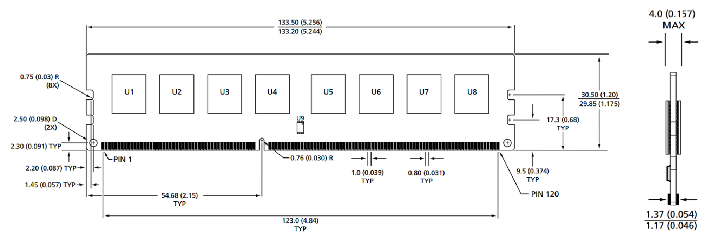
Dimenzije modula
Pogled od spredaj

Pogled od spredaj

Opombe:
1. Vse dimenzije so v milimetrih (palcev); Max/min ali tipičen (tip), kjer je zapisano.
2.Toleranca na vseh dimenzijah ± 0,15 mm, razen če ni drugače določeno.
3. Dimenzijski diagram je namenjen samo referenci.
Kategorije izdelkov : Dodatki za industrijski pametni modul


Izjava o zasebnosti: Vaša zasebnost je za nas zelo pomembna. Naše podjetje obljublja, da ne bo razkrilo vaših osebnih podatkov nobenemu izstopu z izrecnimi dovoljenji.

Izpolnite več informacij, da boste lahko hitreje stopili v stik z vami
Izjava o zasebnosti: Vaša zasebnost je za nas zelo pomembna. Naše podjetje obljublja, da ne bo razkrilo vaših osebnih podatkov nobenemu izstopu z izrecnimi dovoljenji.